A Collector's Guide
Connectors: Blade vs Chassis
Why your blade has fewer rings than the ones in the ads — the difference between a blade connector and a chassis connector, explained.
Last updated: 31 Jul 2026
One of the most common questions newcomers ask is: "Why does my blade have fewer rings than the connectors I see in the ads?" The short answer is that there are two distinct types of connector, each serving a different purpose in the electrical chain between the removable blade and the internal chassis.
Confusing the two is understandable — they look similar and are physically compatible with the same emitter socket — but they carry very different numbers of electrical contacts. Mixing up the terminology leads to wrong purchases and mismatched parts, so it's worth knowing which is which before you buy.
The Blade Connector
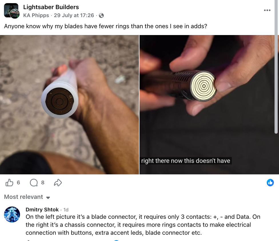
The blade connector (shown on the left in the image below) is the simpler of the two. Because the blade itself only carries the Neopixel strip, it requires just three contacts: Positive (+), Negative (−), and Data. With only three signals to pass through, the connector has fewer concentric rings — typically two visible ring bands plus the centre pin.
This is why a blade that looks "plainer" than the connector in a seller's listing photo is not necessarily wrong or lower quality. The blade side is deliberately minimal because the blade has no buttons, accent LEDs, or displays to drive.
- Contacts: 3 — Positive, Negative, Data
- Found on: the removable blade end / blade-side PCB
- Visual cue: fewer rings, simpler profile
The Chassis Connector
The chassis connector (shown on the right in the image below) is the more complex counterpart. It sits inside the hilt on the removable chassis/core and must carry not only the three blade signals but also the connections for every auxiliary component mounted on the chassis — buttons, accent LEDs, the blade connector itself, and more.
To carry all of those signals through a single mating interface, the chassis connector uses additional concentric rings (often five or more gold-coloured bands). The extra rings are each dedicated to a different auxiliary circuit.
- Contacts: many — blade (+, −, Data) plus auxiliary circuits
- Found on: the chassis / removable core side
- Drives: buttons, accent LEDs, and the blade connector itself
- Visual cue: multiple concentric gold rings
Source Post
The illustration below is a social-media post from the "Lightsaber Builders" Facebook group, originally raised by KA Phipps and clarified in a reply by Dmitry Shtok. It captures the blade-vs-chassis distinction perfectly in a single side-by-side photo.
Dmitry Shtok — reply
"On the left picture it's a blade connector, it requires only 3 contacts: +, − and Data. On the right it's a chassis connector, it requires more rings contacts to make electrical connection with buttons, extra accent leds, blade connector etc."